Calculation of the moment of inertia in Solidworks or Inventor
| In mechanics, the moment of inertia, or moment of mass inertia, expresses the degree of difficulty in changing the state of movement of a rotating body. Generally the unit is Kg.m2 (kilogram-metre square). The further away from the turning center the masses are, the greater the moment of inertia. The calculation of the moment of inertia of your set is one of the main data that we need to know in order to identify which indexing table best suits your need, without running the risk of oversizing it, bringing high costs to your project, or undersizing it, bringing less resistance than your need. There are several ways of knowing the moment of inertia: a) manually, through mathematical calculations We developed the step-by-step below to facilitate the identification of the moment of inertia of your set that will be moved by the indexing table, using the CAD tool Solidworks and Inventor. Other CADs are quite similar in the way of obtaining the calculation. Please check with your CAD manufacturer for the calculation procedure. |  |
Solidworks
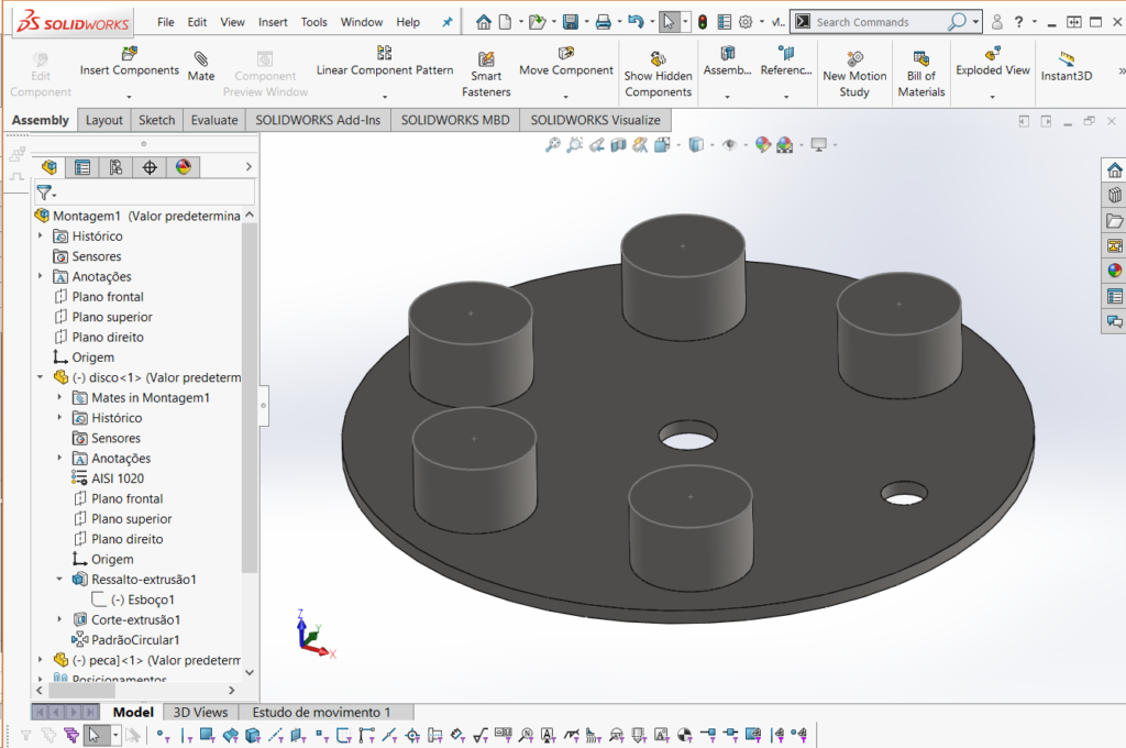
| 1 – Create a new assembly including only the items to be moved by the indexed table (discs, devices, screws, parts etc). All items must have their measurements and total mass well defined |
 |
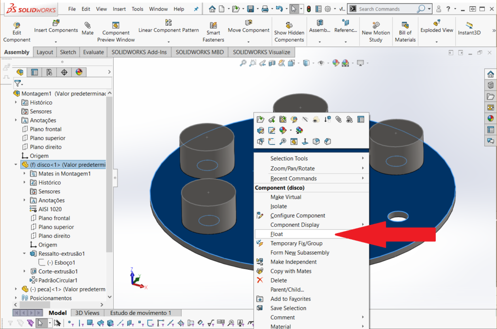
| 2 – Allow the assembly to float by right-clicking over it |
 |
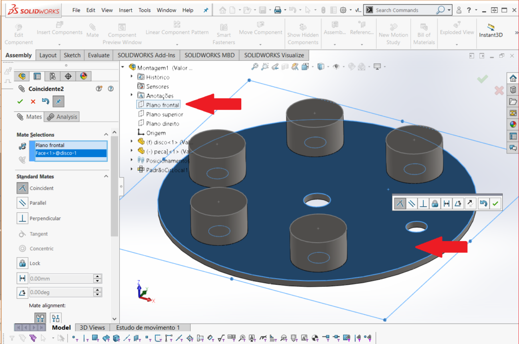
| 3 – Align the moving disc to one of the axials using the Clips icon. Position should be defined as “coincident” |
 |
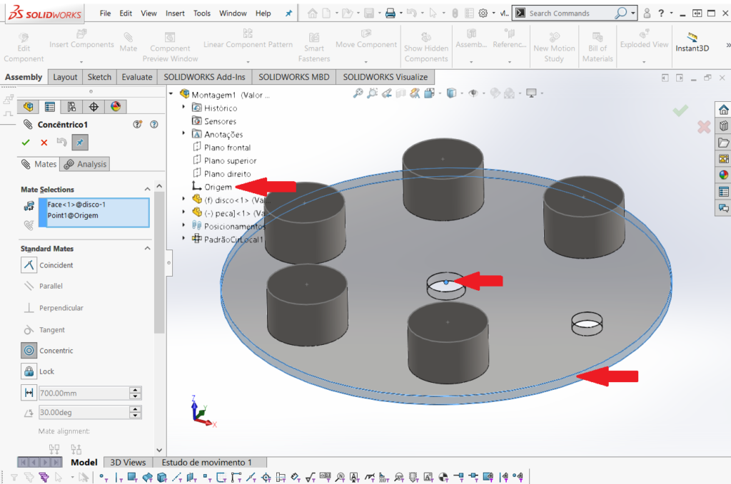
| 4 – Make sure you also align the origin of Solidworks with the center of the spinning disc of your assembly using the Clips icon. The positioning must be of “concentric” type |
 |
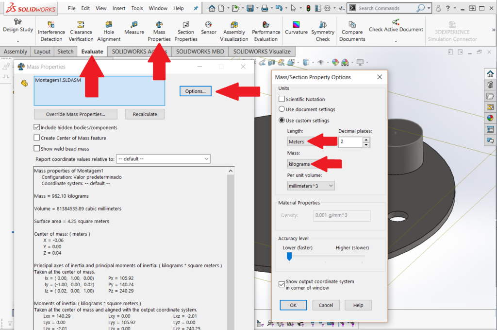
| 5 – Deselect all objects, then go to menu “Evaluate -> Properties of Mass”. When the new screen is ready click onto “Options” and change the unit of measurement for mass to “Kilograms” and length to “Meters” |
 |
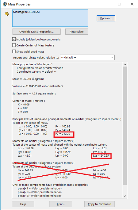
| 6 – Note that Soliworks has now added to the centre of mass of the object a pink-ish UCS. If the assembly is balanced, the UCS will be placed to the center of the part. In the example below you will see an unbalanced assembly. Arrange the assembly so you can see both the moment of inertia and the center of the assembly. It’s important to be able to see X, Y and Z axials of the UCS, as the UCS doesn’t always coincide with the UCS positioned at the bottom left of your Solidworks screen. Press “Print Screen” on your keyboard and send us the image you’ve created including the values for moment of inertia. Find an example of how the image should look below |
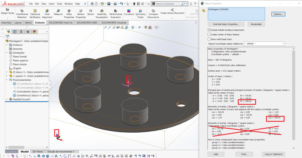 |
| In the example above, the value we are looking is Lzz 240,25 Kgm2, provided the assembly will rotate around axial Z. If the assembly was balanced than Pz and Lzz would have the exact same value |
 |
Inventor
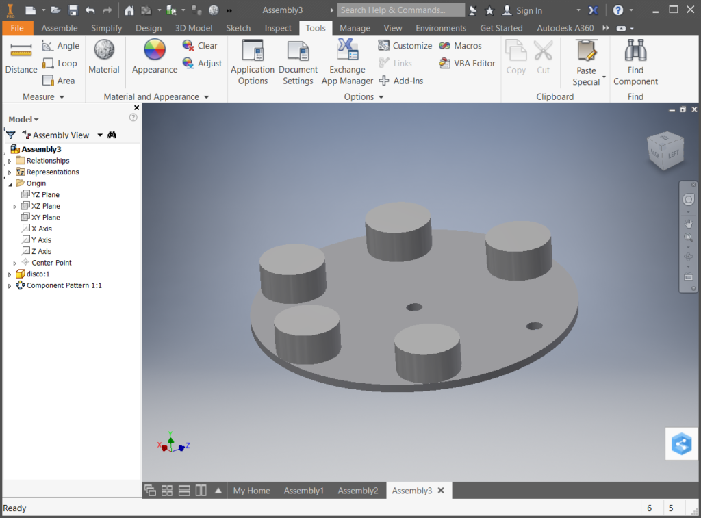
| 1 – Create a new assembly including only the items to be moved by the indexed table (discs, devices, screws, parts etc). All items must have their measurements and total mass well defined |
 |
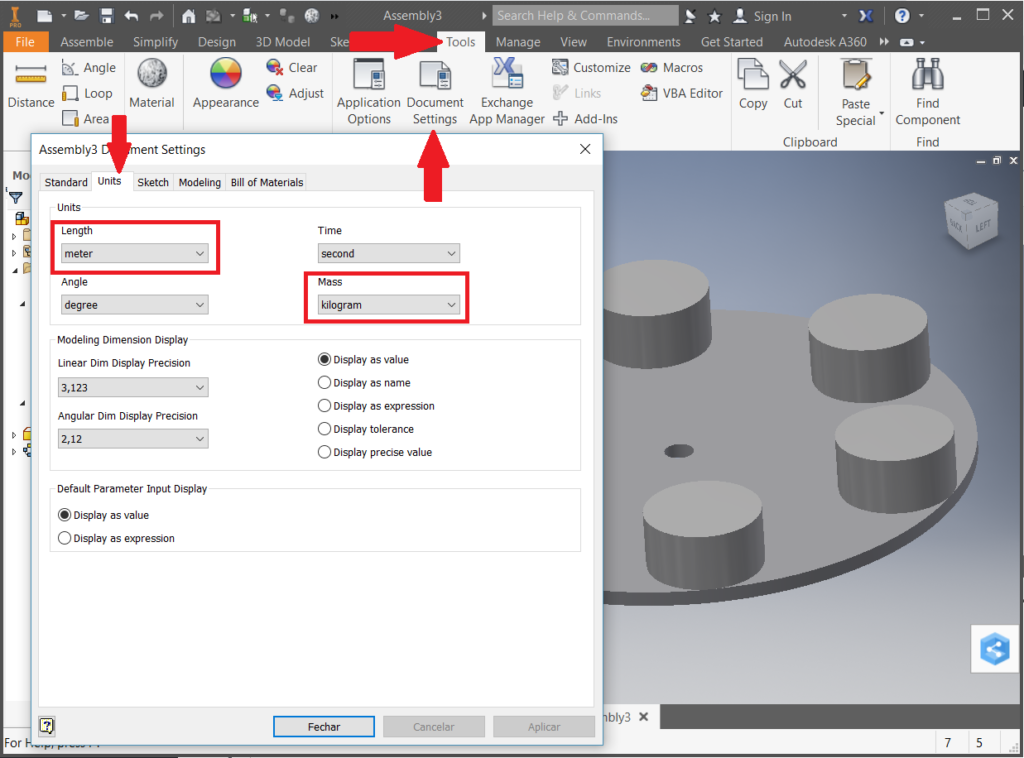
| 2 – Change the units, using the “Tools / Document Settings” menu. In the document properties screen, click on “Units” and change the units Length to meter and Mass to Kilogram |
 |
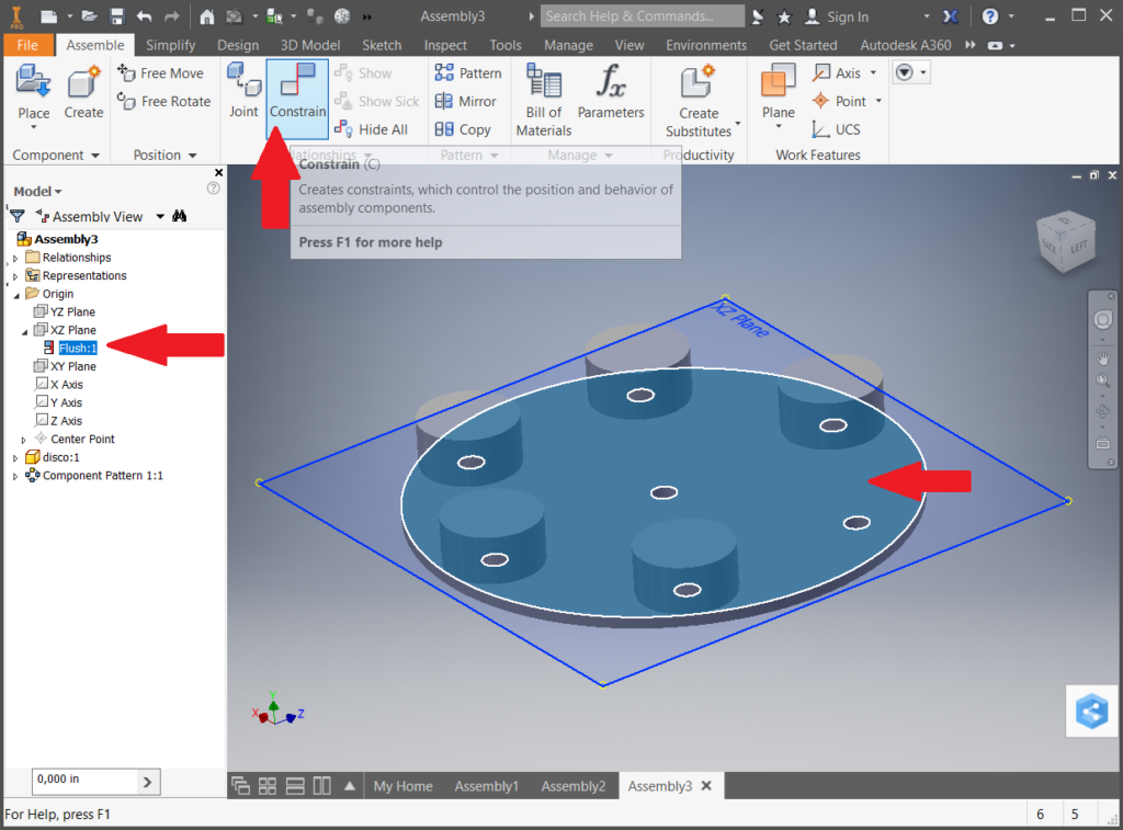
| 3 – Align the rotating disk of the assembly in the XZ plan using the “Constrain” icon |
 |
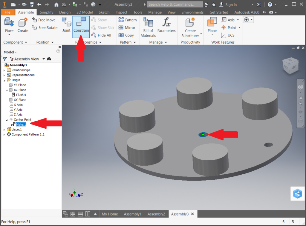
| 4 – Also align the Inventor Origin with the center of the assembly’s rotating disk using the “Constrain” icon |
 |
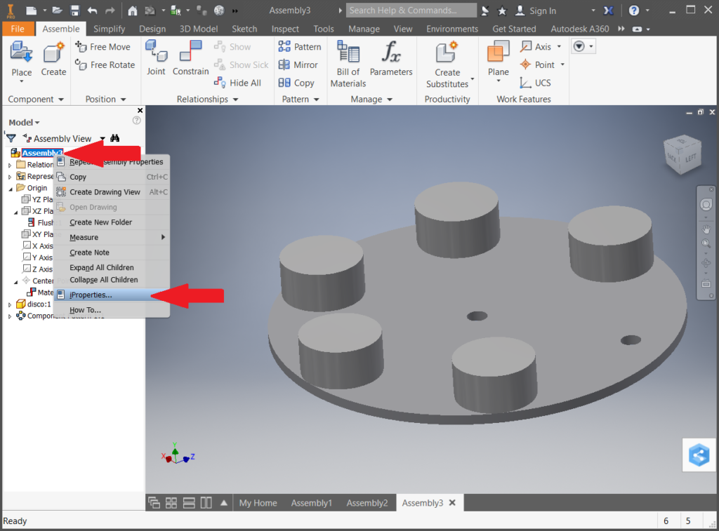
| 5 – With the right mouse button, click the first menu item on the left and then click the left mouse button on the “iProperties” submenu and a new assembly properties screen will appear |
 |
| 6 – In this new properties screen, click on the “Physical” tab, then the “Update” button and then the “Main” button. The values of the moment of inertia related to the objects that will rotate around the Y axis are represented in box I2. Click on the “Print Screen” button on your computer and send the image of the piece + moment of inertia to Posibras. The image below is an example of how it should be sent |
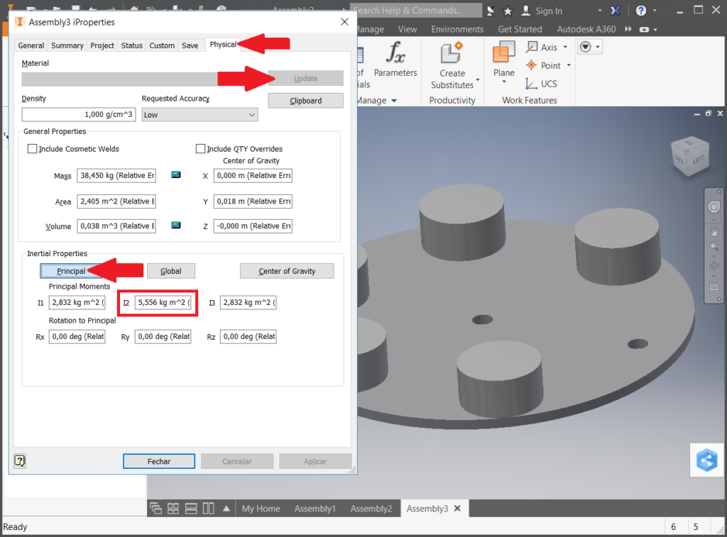 |
| In the example above, the value we are looking for is I2 5.556 Kg.m2, since the assembly will rotate on the Y axis. If the units of the moment of inertia is different from Kg.m2, it is necessary to perform steps 2, 5 and 6 |